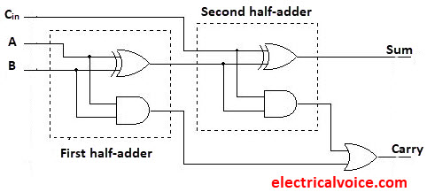

The main difference between the Full Adder and the previous Half Adder is that a full adder has three inputs. Then a Carry-in is a possible carry from a less significant digit, while a Carry-out represents a carry to a more significant digit.Ī full adder circuit is designed in such a manner that can take eight inputs together to create a byte-wide adder and cascade the carry bit from one adder to the another.

The full adder is a logical circuit that performs an addition operation on three binary digits and just like the half adder, it also generates a carry out to the next addition column. One simple way to overcome this problem is to use a Full Adder type binary adder circuit. The most complicated operation the half adder can do is “1 + 1” but as the half adder has no carry input the resultant added value would be incorrect. আরো পড়ুন :: Second Chapter Lesson-9: Network Devices.įor example, suppose we want to add together two 8-bit bytes of data, any resulting carry bit would need to be able to “ripple” or move across the bit patterns starting from the least significant bit (LSB). One major disadvantage of the Half Adder circuit when used as a binary adder, is that there is no provision for a “Carry-in” from the previous circuit when adding together multiple data bits.
HALF ADDER TRUTH TABLE AND CIRCUIT CODE
It is mainly designed for the addition of binary number, but they can be used in various other applications like binary code decimal, address decoding, table index calculation, etc. 5. You will be able to explain binary adder circuit.Īn adder is a combinational circuit or digital circuit in electronics that implements or performs addition of numbers.You will be able to implement Full adder circuit using Half adder circuit. You will be able to describe Full Adder circuit. You will be able to describe Half Adder circuit. You will be able to explain Adder circuit.


 0 kommentar(er)
